

Channel CPACK Utility
The channel CPACK utility core is meant to allow one or more channels to be enabled by software without any padding. This allows full usage of the DMA bandwidth without any overhead. This core normally works with an ADC and DMA modules. The ADC interface is channel based (one interface per each ADC channel) and consists of enable, valid and data signals. The DMA interface is a single FIFO interface consisting of valid and data signals. The enable signals are usually controlled by software. The core simply packs the ADC data of the individual channels into a single data bus, as defined by the ADC enables.
Features
Supports Altera and AMD Xilinx devices
Supports up to 64 channels
Supports configurable channel data width
Files
Name |
Description |
|---|---|
Verilog source for the peripheral. |
Configuration Parameters
Name |
Description |
|---|
Interface
Name |
Description |
|---|---|
packed_fifo_wr |
FIFO interface to the DMA (sink). |
fifo_wr_en |
Indicates that at least one payload from fifo_wr_data_* is valid. |
enable_* |
Indicates the status of the channel, if asserted the channel is active. |
fifo_wr_data_* |
ADC data bus from the ADC core. |
Detailed Description
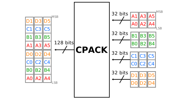
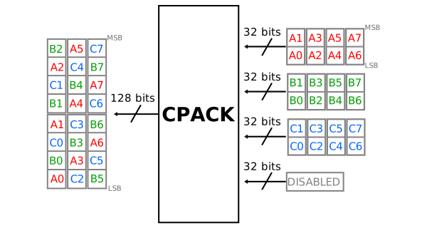
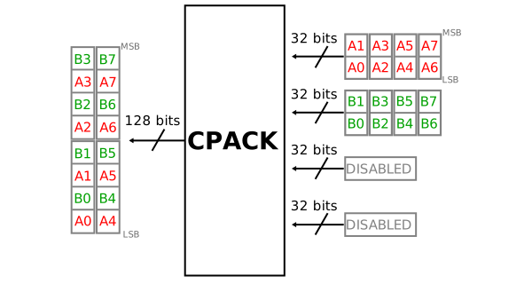
The core “collects” samples from the ADC interface and passes it to the DMA (or any other sink module), the data flow is controlled by the ADC. This is best explained through some examples. Let’s consider a 4 channel ADC with a channel data width of 32 bits. The ADC core provides two 16-bit samples on its output for all channels when the valid is asserted. The DMA interface, in this case, is an interleaved 8 samples (128 bits) stream. This is because irrespective of the ADC channel data width, the software always sees data as “samples interleaved”. The same data set may received by the DMA core with a channel width of 128 bits or 16 bits.
References
HDL IP core at library/util_pack/util_cpack2