

AXI PWM Generator
The AXI PWM Generator core is used to generate a maximum of 16 configurable signals (Pulse-Width Modulations). The pulses are generated according to the state of a counter; there is one counter for each pulse.
Features
Up to 16 configurable signals (period, width, offset)
External synchronization
External clock
Files
Name |
Description |
|---|---|
SystemVerilog source for the top module |
|
Verilog source for a channel module |
|
SystemVerilog source for regmap |
|
Dynamic constraint file (AMD tools) |
|
Constraint file (Intel tools) |
|
IP definition file (AMD tools) |
|
IP definition file (Intel tools) |
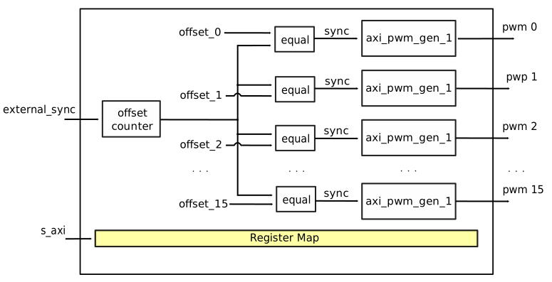
Block Diagram
Configuration Parameters
Note
The pulse period, width and offset are set in number of clock cycles. The clock is the AXI clock or if activated, the external clock.
Name |
Description |
|---|---|
ID |
Core ID should be unique for each IP in the system |
ASYNC_CLK_EN |
Use external clock, asynchronous to s_axi_aclk (1). Otherwise, use internal clock, s_axi_aclk (0). |
N_PWMS |
Number of pulses/pwms |
PWM_EXT_SYNC |
PWM offset counter uses external sync |
EXT_ASYNC_SYNC |
The external sync for pulse 0 is asynchronous |
SOFTWARE_BRINGUP |
Require software, to bring the core out if reset |
EXT_SYNC_PHASE_ALIGN |
Set default flag value for external sync phase align feature |
FORCE_ALIGN |
Set default flag value for force align feature |
START_AT_SYNC |
Set default flag value for start at sync feature |
Interface
Name |
Description |
|---|---|
ext_clk |
External clock. |
ext_sync |
External sync signal, synchronizes pulses to an external signal. |
pwm_* |
Output PWM, up to 16, indexed from 0 to 15. |
Detailed Description
Let’s start with some basic notions:
The pulse generators are based on incrementing counters.
The pulse period starts on the high level interval and ends on the low level.
By default, all counters start at the same time. When a different phase (delay) is needed between the pulses, we can set an offset.
The offset feature can synchronize channels 0 to 15 relative to an offset counter.
The offset counter will wait for a HIGH -> LOW transition of the synchronization pulse (‘’load_config’’ or ‘’ext_sync’’). For more info see the below channel phase alignment feature.
To disable a PWM channel, write 0 to its
periodregister.The duty cycle is the ratio between pulse width over pulse period.
The following features can be enabled by setting a flag in the register REG_UP_CONTROL(0x18):
Channel phase alignment
The AXI PWM Generator core can be synchronized by an external signal on the HIGH -> LOW transition of the ext_sync signal.
The external sync can be used in two modes, based on the external sync align feature:
external_sync_align flag is set(1) the ext_sync will trigger a phase align at each neg-edge.
otherwise the phase align must be armed by a load config toggle, while the external sync must be held HIGH.
Software bringup (software reset)
If set, the software must bring the core out of reset, after a system reset, for the pwm signals to be generated.
Force align
If set, the current active pulses are immediately stopped and realigned. Otherwise, the synchronized pulses will start only after all running pulse periods end. Software overwritable at runtime.
Start at sync
If active, the pulses will start after the trigger event. Otherwise each pulse will start after a period equal to the one for which it is set. Software over writable at runtime.
This flags are software overwritable at runtime. Default value is given at build time.
software bringup = 1
start at sync = 1
force align = 0
ext sync align = 0
Timing Diagrams and examples
Note
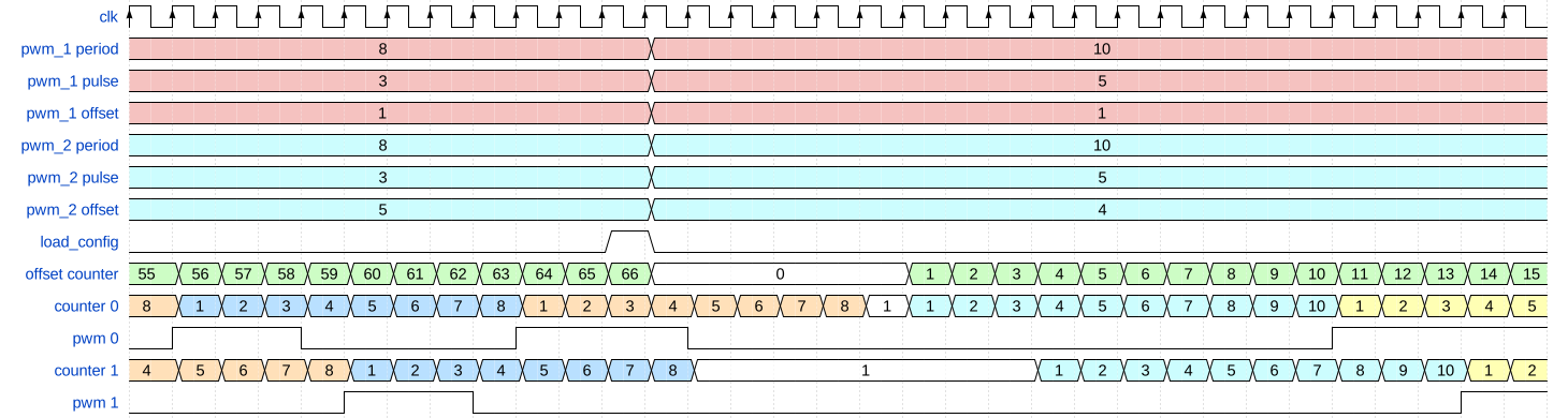
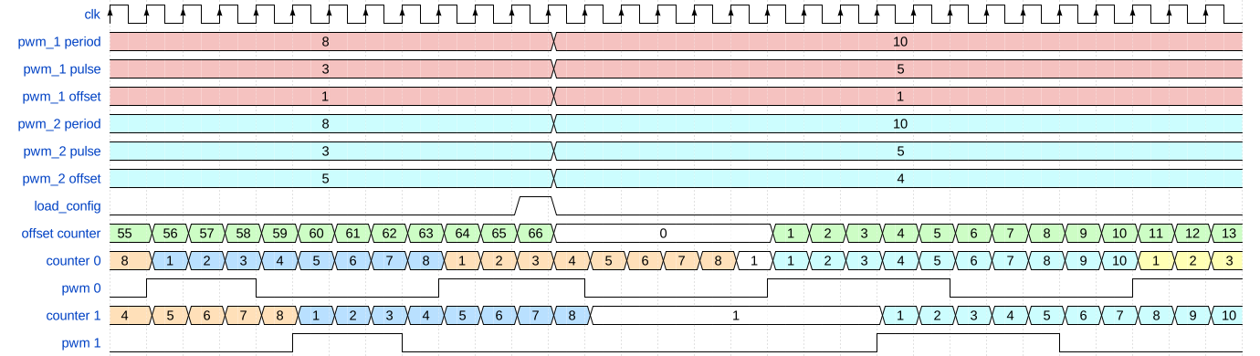
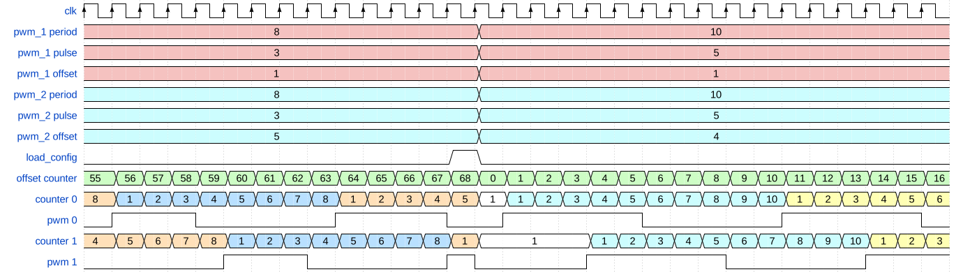
The diagrams below, that refer to load_config functionality, are
highlighting the transition from a set of pwm core config values (period,
pulse, offset) to new pwm set of config values.
Warning
The relationship between the offset and channel counters is not 100% accurate. It is meant to highlight the functionality, by helping the reader track the pwm waveforms. If you are interested in the exact timing you will have to simulate the IP.
The timing diagram below, shows the load_config functionality with
force align and start at sync disabled.
The timing diagram below, shows the load_config functionality with
force align disabled and start at sync enabled.
The timing diagram below, shows the load_config functionality with
force align and start at sync enabled.
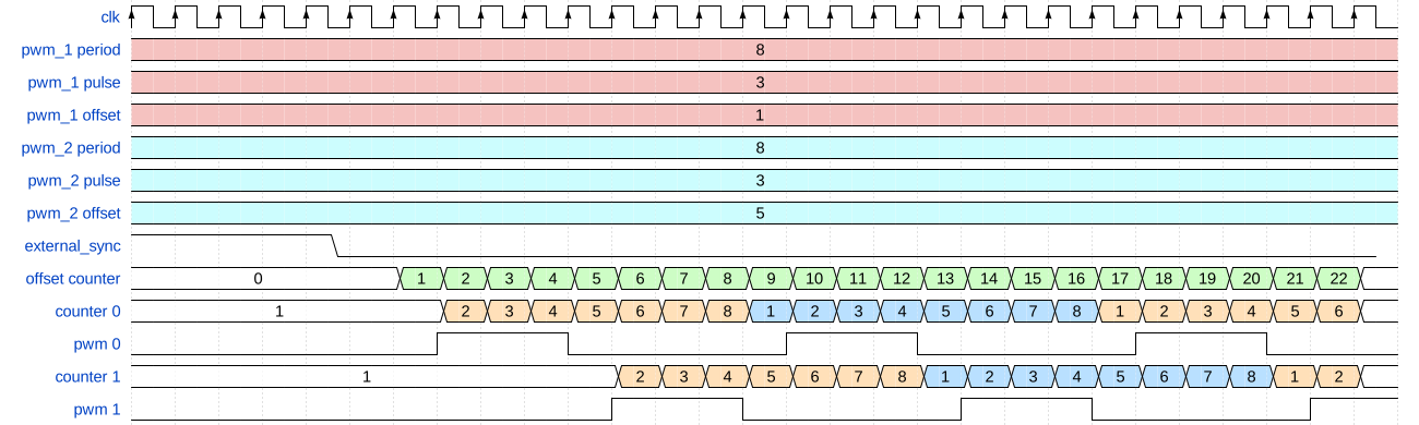
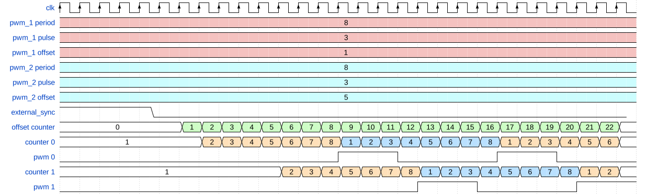
The below timing diagrams, shows the external_sync functionality:
Register Map
Address |
Reg Name |
|||||
|---|---|---|---|---|---|---|
HDL |
DWORD |
BITS |
Field Name |
Type |
Default Value |
Description |
0x0 |
0x0 |
VERSION |
Version and Scratch Registers |
|||
[31:0] |
VERSION |
RO |
0x00020101 |
Version number. Unique to all cores. |
||
0x1 |
0x4 |
ID |
Core ID |
|||
[31:0] |
ID |
RO |
0x00000000 |
Instance identifier number. |
||
0x2 |
0x8 |
SCRATCH |
Version and Scratch Registers |
|||
[31:0] |
SCRATCH |
RW |
0x00000000 |
Scratch register. |
||
0x3 |
0xc |
CORE_MAGIC |
Identification number |
|||
[31:0] |
CORE_MAGIC |
RW |
0x601a3471 |
Identification number. |
||
0x4 |
0x10 |
RSTN |
Reset and load values |
|||
[1] |
LOAD_CONFIG |
WO |
0x0 |
Loads the new values written in the config registers. |
||
[0] |
RESET |
RW |
0x1 |
Reset, default is (0x1). The default value can be changed by HDL at build time, using SOFTWARE_BRINGUP parameter. |
||
0x6 |
0x18 |
CONFIG |
Features enable register |
|||
[2] |
EXT_SYNC_PHASE_ALIGN |
RW |
0x0 |
If active, the ext_sync will trigger a phase align at each neg-edge. Otherwise the phase align will be armed by a load config toggle. This is set by default in HDL, but can be overwritten by software. |
||
[1] |
FORCE_ALIGN |
RW |
0x0 |
If active the current active pulses are immediately stopped and realigned. Otherwise, the synchronized pulses will start only after all running pulse periods end. |
||
[0] |
START_AT_SYNC |
RW |
0x1 |
If active, the pulses will start after the trigger event. Otherwise each pulse will start after a period equal to the one for which it is set. Default valew can be overwritten at build time through parameters. |
||
0x5 |
0x14 |
NB_PULSES |
Number of pulses |
|||
[31:0] |
N_PWMS |
RO |
0x00000001 |
Number of configurable pulses. |
||
0x10 + 0x1*n |
0x40 + 0x4*n |
PULSE_n_PERIOD |
Pulse n period Where n is from 0 to 15. |
|||
[31:0] |
PULSE_PERIOD |
RW |
0x0000000a |
Pulse duration, defined in number of clock cycles. |
||
0x20 + 0x1*n |
0x80 + 0x4*n |
PULSE_n_WIDTH |
Pulse n width Where n is from 0 to 15. |
|||
[31:0] |
PULSE_WIDTH |
RW |
0x00000007 |
Pulse width (high time), defined in number of clock cycles. |
||
0x30 + 0x1*n |
0xc0 + 0x4*n |
PULSE_n_OFFSET |
Pulse n offset Where n is from 0 to 15. |
|||
[31:0] |
PULSE_OFFSET |
RW |
0x00000000 |
Pulse offset, defined in number of clock cycles. |
||
Access Type |
Name |
Description |
|---|---|---|
RO |
Read-only |
Reads will return the current register value. Writes have no effect. |
RW |
Read-write |
Reads will return the current register value. Writes will change the current register value. |
WO |
Write-only |
Writes will change the current register value. Reads have no effect. |
References
HDL IP core at library/axi_pwm_gen