Read and write device registers in the Memory Map
By the end of this page you will have read a device's registers into Evaluation Studio, changed a value, written it back to hardware, and confirmed the change took effect.
What the Memory Map shows
The Memory Map is a grid of the registers your device exposes. Each register sits at an
address and holds a fixed number of bits; the rows nested beneath it are its bit
fields, the named slices of that register that actually mean something (SW_Reset,
Operating_Modes, and so on). Expand a register to see its fields.
- Access —
RWfor readable and writable,ROfor read-only. Read-only rows are skipped when writing, without an on-screen message. - Value — the value held in Evaluation Studio, which is not necessarily what is on the device. A row shown in bold is dirty: you have edited it and not yet written it. Reading or writing a register clears its dirty state.
- Registers, fields, addresses, access and functional groups are all declared by the
plug-in's
.spacefile. Nothing in this view is editable structure — only values.
Before you start
- Evaluation Studio running, with your board connected and its device open.
- A plug-in that declares a memory map. Select Memory Map in the Explorer on the left.
- A plug-in that declares no register controller opens in virtual mode: the grid is fully interactive but reads and writes never reach hardware. See Troubleshooting if values never change.
Steps
-
Select Memory Map in the Explorer. The grid lists every register in the device's register maps. Each register map is a top-level row named after the map itself —
SPI, for example — with its registers nested beneath it.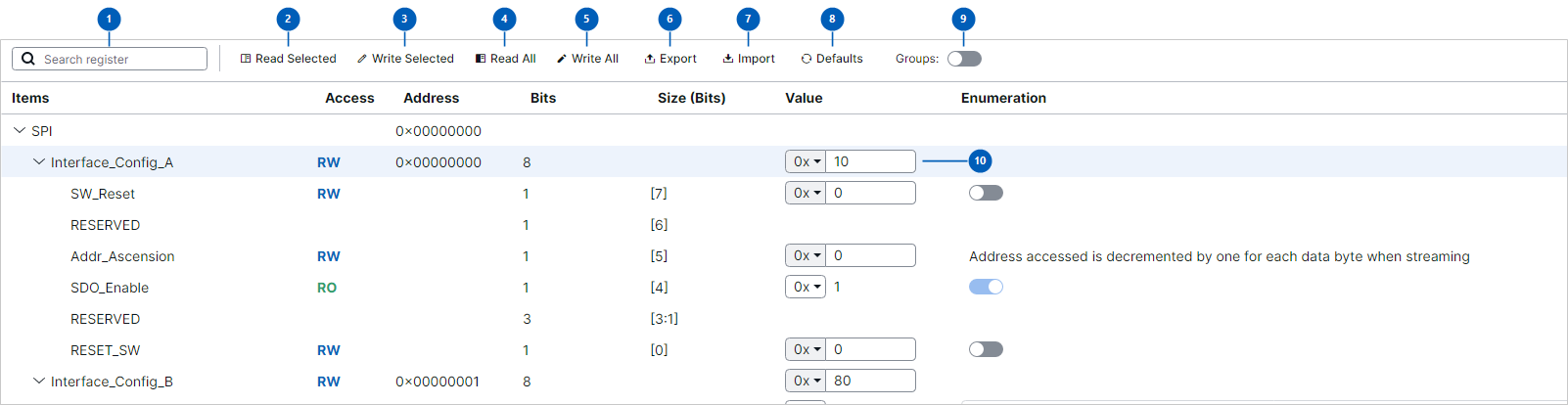 The Memory Map for the ETC 2025 demo plug-in. The toolbar controls are numbered in the
reference table below.
-
Click Read All to sync the whole map from hardware. Every value now reflects the device, and no row is bold.
-
Find the register you want. Type into Search register (1) to filter the grid, then click the chevron beside a register to expand its bit fields.
-
Set the radix before you type. Each Value cell (10) has its own dropdown reading
0xfor hex orDfor decimal — it is per cell, not a setting for the whole view. Type the value in the field's own format, with no prefix: in an0xfield,80means 0x80.Some bit fields render as a toggle switch or an enumeration dropdown, depending on what the
.spacefile declares for them — see the register details window. -
Edit the value. The row turns bold, and so does its parent register — the edit is held in Evaluation Studio, not yet on the device.
-
Write it. Select the row you edited and click Write Selected (3), or click Write All (5) to write every dirty writable register in the map.
-
Switch views with the Groups toggle (9), if your device declares functional groups — related bit fields collected across registers. The group view is a separate grid with its own selection: rows you selected in the register view are not selected here, and vice versa. The toggle does not appear when the
.spacefile declares no groups.
Toolbar reference
| # | Control | What it does |
|---|---|---|
| 1 | Search register | Filters the grid by register name. |
| 2 | Read Selected | Reads the registers implied by the selected rows in the visible grid. Access is deliberately ignored — a read is issued a whole register at a time, so a write-only field is not dropped along with its readable siblings. |
| 3 | Write Selected | Writes the selected rows that have write access. Read-only registers are skipped whole; read-only bit fields are dropped individually, so a mixed selection still writes the writable fields. |
| 4 | Read All | Reads every register in every register map, in address order. Ignores selection, access and dirty state. |
| 5 | Write All | Writes every register that is both writable and dirty. A register you have not edited is not written. |
| 6 | Export | Prompts you to pick which register map to save, then writes the current values to a .csv file and offers to show it in File Explorer. |
| 7 | Import | Loads register values from a previously exported .csv. Warns if the file would overwrite a read-only register. |
| 8 | Defaults | Resets every value to the default declared in the .space file. This changes the values in the view only — write them to send them to the device. |
| 9 | Groups | Switches between the register-map view and the functional-group view. Present only when the device declares functional groups. |
| 10 | Value editor | The value, plus a per-cell radix dropdown: 0x (hex) or D (decimal). |
What "selected" resolves to
Selection is read from whichever grid is visible, and rows resolve to registers like this:
- A register row → that register.
- A bit field row → its parent register; reads are always whole-register.
- A register-map or group header row → everything beneath it.
- Selecting a register and its own bit fields writes the full register once — the register row wins. If that register is read-only, nothing is written: the write is refused rather than quietly downgraded to a partial write of the fields.
- An empty selection does nothing at all, with no error.
The register details window
For a fuller view of one register, hover over its Value cell in the grid and click the
icon button that appears at the cell's right edge. The register opens in its own window,
showing every bit field at once with the widget the .space file declares for it.
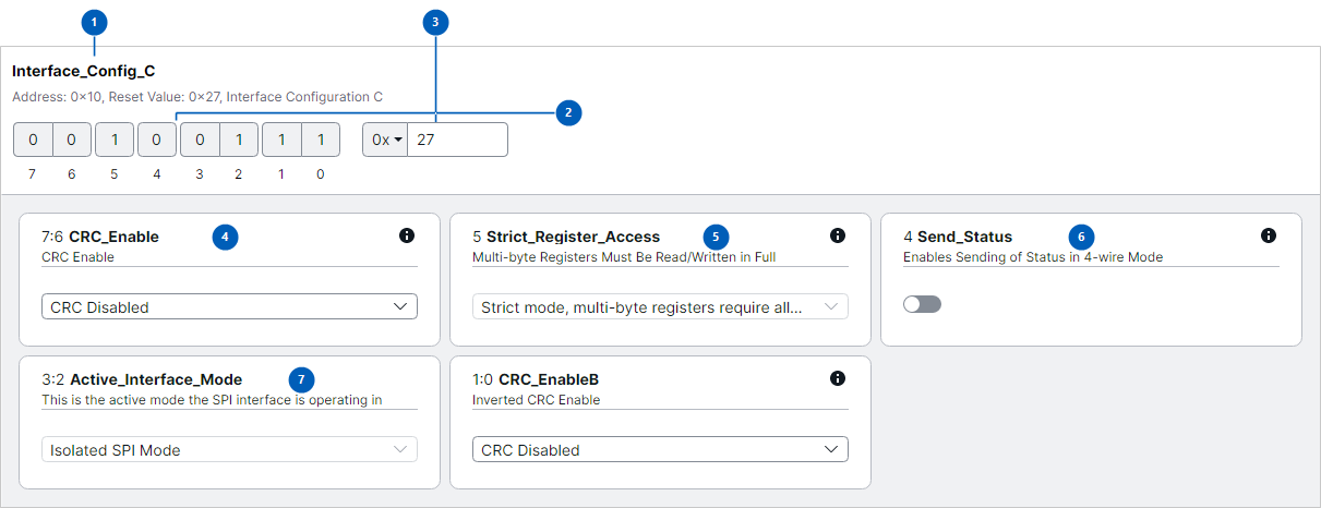 The details window for
Interface_Config_C in the ETC 2025 demo plug-in.
| # | Area | What it shows |
|---|---|---|
| 1 | Register heading | The register name, its Address, its Reset Value from the .space file, and its description. |
| 2 | Binary bit editor | One cell per bit, most significant first, numbered beneath. Click a cell to flip that bit. Bits belonging to a read-only field are greyed out and cannot be clicked. |
| 3 | Register value | The whole register's value, with the same per-cell radix dropdown as the grid. Editing here and flipping bits in (2) are two views of one value — each updates the other. |
| 4 | Writable enumeration field | 7:6 CRC_Enable. The bit slice precedes the name. A field with named values renders as a dropdown. |
| 5 | Read-only field | 5 Strict_Register_Access. Declared R in the .space file, so the control is disabled — unlike the grid, where a read-only cell still accepts typing and the edit is dropped at write time. |
| 6 | Boolean field | 4 Send_Status. A single-bit field declared as a checkbox renders as a toggle switch. |
| 7 | Read-only enumeration field | 3:2 Active_Interface_Mode. Also disabled. |
The ⓘ icon on a card shows the field's documentation from the .space file. It is absent
when the file declares none for that field — as on card (7). Edits made here are held in
Evaluation Studio exactly like grid edits: the register goes dirty, and you still have to
write it.
Verify
- Click Read All. No row is bold — every value matches the device.
- Edit one writable bit field. That row and its parent register both turn bold.
- Select that row and click Write Selected. The bold clears, because the write synced the register.
- Click Read All again. The value reads back as what you wrote.
- To confirm the whole register, not just the field, check the register row's own Value cell — it shows the composed value, with your field's bits in place. Or open the register details window and read the bit editor directly.
If step 4 reads back the old value, the write did not reach the device — start with the Troubleshooting table below.
Troubleshooting
| Symptom | Cause | Fix |
|---|---|---|
| Read Selected or Write Selected does nothing, and there is no error | Nothing is selected in the grid that is currently visible. An empty selection is a silent no-op. | Select a row and retry. If you flipped Groups after selecting, your selection is in the other view — the two grids have separate selections. |
| Write All does nothing | No register is both writable and dirty. | Check that at least one row is bold. Read-only registers are never written. |
| Bits outside the field you wrote came back as reset values | The register had never been read, so the bits outside your selection were composed from the .space reset value rather than a hardware reading. |
Click Read All, then write again. Always read before writing individual bit fields. |
| A field you edited was not written | Write Selected only writes the slices you selected; a dirty but unselected sibling field is left out. | Select every field you want committed, or use Write All. |
| You selected a read-only register and one of its writable fields, and nothing was written | The register row claims the address and is then refused. There is no partial-write fallback, by design. | Select just the bit field, not its parent register. |
| An edit to a bit field is ignored | The field is read-only (RO in the Access column) and is dropped from the write without any message. |
Check the Access column. Read-only fields cannot be written. The register details window disables read-only fields outright, so it is the quicker way to see which fields you can actually change. |
| A value is wrong by orders of magnitude | The radix dropdown was on the other mode — 255 typed in a D field is not FF. |
Check the 0x / D dropdown on that cell, then re-enter the value. |
| The Groups toggle is missing | The plug-in's .space file declares no functional groups. |
Nothing to fix; this device has only the register-map view. |
| Reads and writes report success but the hardware never responds | The plug-in declared no register controller, so the Memory Map is in virtual mode. | Check the log for Running in virtual mode: no register controller supplied. See Logs. |
Related
- Logs — finding the log messages named above.