Scalable Phased Array & Adaptive RF Systems Enabled by ADI DataX™
Complex RF needs a faster path from idea to array. ADI DataX accelerates Software Defined Radio (SDR) systems-based development by simplifying evaluation across platforms like ADALM-PHASER, Jupiter SDR, and Talise SOM. These platforms support synchronized MIMO scaling and rapid prototyping for complex RF architectures. Designers can use various abstraction layers that streamline data acquisition and system optimization. This unified workflow speeds the creation of adaptive, high-performance RF solutions.
Resources
Holohub: Jupiter Holohub Project
Matlab: Talise Matlab Project
Hardware:
Required Software
-
With Transceiver Toolbox add-on installed using the add-on explorer in Matlab.
Block diagram
Demo description
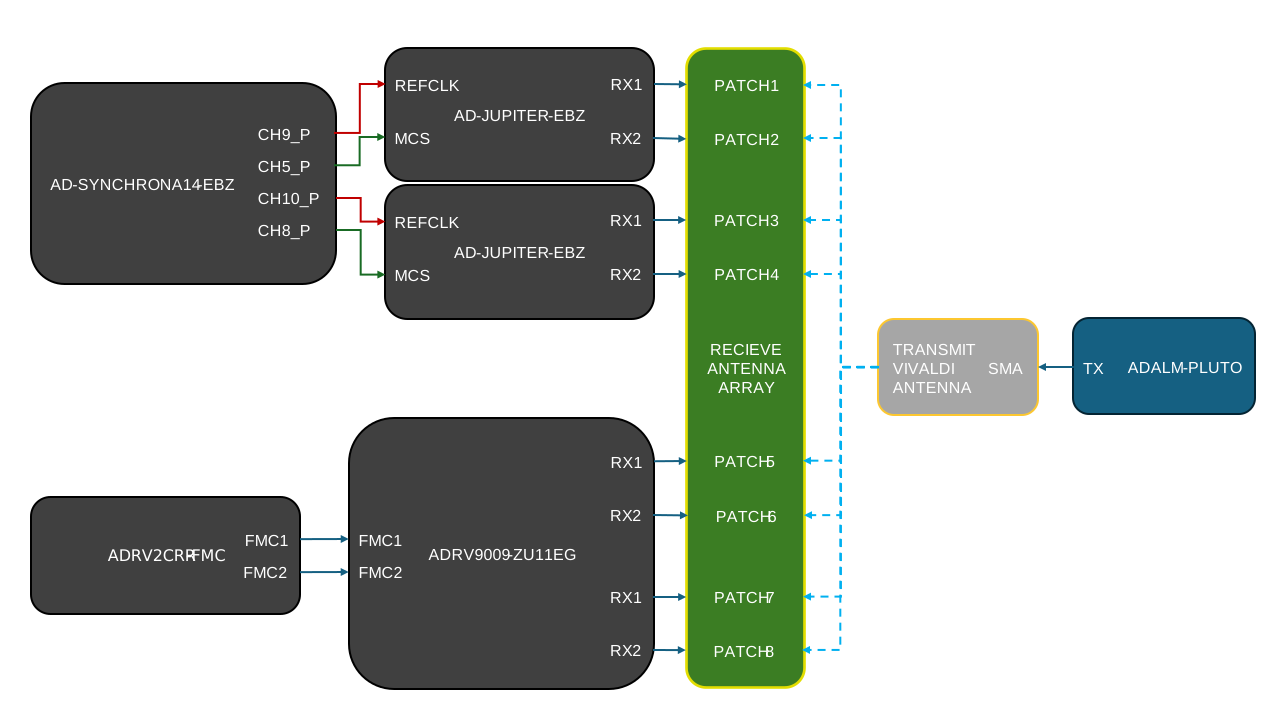
This demo illustrates the implementation of a monopulse tracking system using ADI’s DataX™, showcasing the platform independence and scalability of our systems. The demo consists of two main systems: the transmitter and the receiver system.
The transmitter system is using an ADALM-PLUTO to generate an RF signal, which is then transmitted through a wideband Vivaldi antenna.
The receiver system uses two separate platforms to showcase the capabilities of DataX™, and the ease of scaling and prototyping across different platforms.
The first receiver system is based on the AD-JUPITER-EBZ, which is a versatile software-defined platform based on ADRV9002 and AMD Xilinx Zynq UltraScale+ MPSoC. ADRV9002 is a new generation RF transceiver that has dual-channel transmitters, dual-channel receivers covering 30 MHz to 6 GHz frequency range with very good RF linearity performance and a set of advanced features like fast profiles switching, flexible power vs performance configuration, fast frequency hopping, multi-chip synchronization and DPD for narrow and wide band waveform. This demo heavily depends on the multi-chip synchronization (MCS) capabilities of the ADRV9002, which allows the usage of two AD-JUPITER-EBZ, synchronized using the AD-SYNCHRONA14-EBZ to create a 4-channel receiver system.
The second receiver system is based on the ADRV9009-ZU11EG RF-SOM, a highly integrated RF System-On-Module (RF-SOM) based on the ADRV9009 and AMD Xilinx Zynq UltraScale+ MPSoC. The RF-SOM is a platform for evaluation and prototyping. To use the RF-SOM a carrier board is required, the ADRV2CRR-FMC board is designed for this purpose.
As for the software, the demo is implemented using Holohub and Matlab. Both applications run on a host computer and stream the data from the hardware over the network: the Holohub implementation controls the Jupiter platforms, while the Matlab implementation controls the RF-SOM platform. Both implementations are using DataX™, which allows for easy prototyping and scaling across different platforms.
But what is Monopulse Tracking?
The name refers to its ability to extract range and direction from a single signal pulse. The method uses two simultaneous beams, the SUM and DELTA beams, to compare the received signal’s amplitude and phase, enabling precise angle estimation. This technique is widely used in radar and communication systems for accurate target tracking and direction finding.
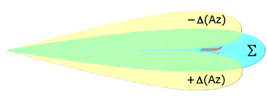
The SUM beam captures the total signal strength, while the DELTA beam measures the difference in signal strength between the two halves of the antenna array. The SUM beam has a maximum when pointed directly towards the transmitter, while the DELTA beam can be:
Δ ≈ 0, when the signal arrives from mechanical boresight
Δ > 0, when the signal arrives from the left of the mechanical boresight
Δ < 0, when the signal arrives from the right of the mechanical boresight
Correlating the SUM and DELTA beams results in an error, which is the difference between the actual angle of arrival and the electrical boresight. By calculating the phase of this error signal, the system can estimate the angle of arrival of the incoming signal with high precision, even in environments with significant noise and interference.
After the angle of arrival is estimated, the phased array can be electrically steered to point towards the transmitter, by adjusting the phase of the signals received by each antenna element.
Important
The monopulse tracking technique is extremely sensitive to the phase and amplitude balance of the antenna array, as well as the calibration of the system. Any imbalance or miscalibration can lead to errors in the angle of arrival estimation, which can degrade the performance of the tracking system.
Before doing the monopulse tracking, it is important to calibrate the system and make sure that you are using a well balanced antenna array.
Required Hardware
Component |
Role |
Quantity |
Notes |
|---|---|---|---|
AD-SYNCHRONA14-EBZ |
The main clock source for the AD-JUPITER-EBZs. |
1 |
Sources the reference clock and the Multi-chip Synchronization signals. |
AD-JUPITER-EBZ |
The platform for the Holoscan implementation. |
2 |
Samples the incoming signals and performs the digital signal processing. |
ADRV9009-ZU11EG RF-SOM |
The platform for the Matlab implementation. |
1 |
Samples the incoming signals and performs the digital signal processing. |
ADRV2CRR-FMC |
The carrier board for the RF-SOM. |
1 |
Provides the necessary interfaces and power for the ADRV9009-ZU11EG RF-SOM. |
ADALM-PLUTO |
The transmitter platform. |
1 |
Generates the transmitted RF signal. |
SD Card Configuration
For the ADRV9009-ZU11EG RF-SOM platform, write the Kuiper image to an SD card, as described at Writing the Image to an SD Card, and copy the ADRV9009-ZU11EG boot files to the boot partition, as described at ADI Evaluation Boards.
For the AD-JUPITER-EBZ platform, begin by writing the image to an SD card the same way as for the ADRV9009-ZU11EG, then copy the files from the following zip to the boot partition of the SD card:
For the AD-SYNCHRONA14-EBZ, the SD card should be flashed as before and the device tree overlay from the following zip should be copied to the
overlaysdirectory of the boot partition of the SD card:Then, load the
rpi-ad9545-hmc7044overlay as described at Raspberry Pi.Lastly, for the ADALM-PLUTO, the firmware should be updated, as described at Firmware Updates. The demo transmits at 5.4 GHz, which is outside of the default tuning range of the ADALM-PLUTO (325 MHz to 3.8 GHz), so the device must be configured in AD9364 mode, as described at Customizing the ADALM-PLUTO. Then, the files from the following zip should be copied to a flash drive:
For additional information please visit USB OTG.
Results
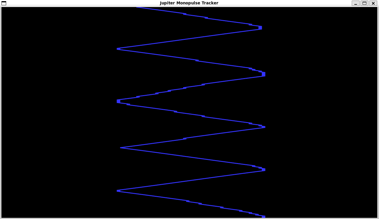
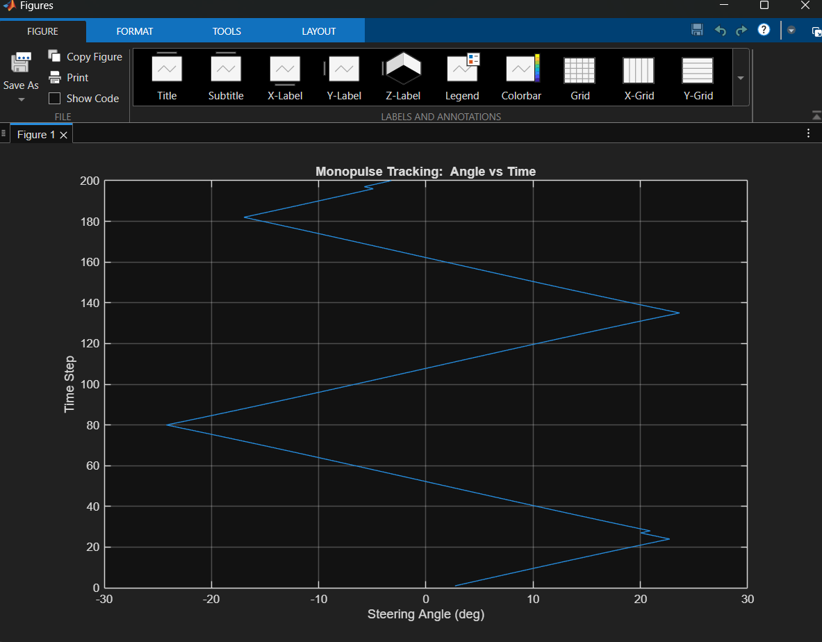
Here are presented the plotted results of the demo. On the X axis the angle of arrival is presented, while on the Y axis the time is presented, to make a waterfall type of plot.