DMA Loopback
Overview
The purpose of this testbench is to test the library/axi_dmac IP in loopback mode.
The entire HDL documentation can be found at AXI DMAC.
Block design
The block design is based on the test harness and two axi_dmac instances, one for the RX side and one for the TX side.
Block diagram
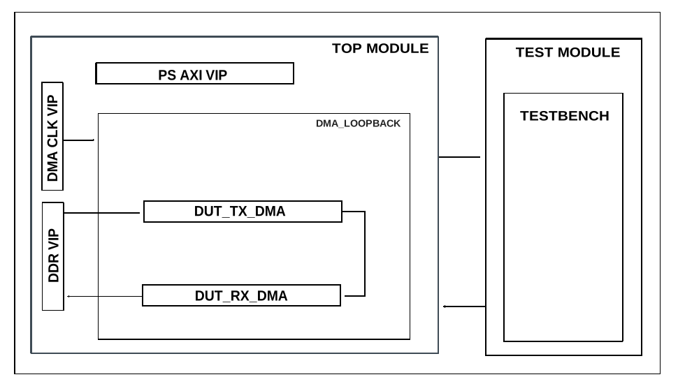
Configuration parameters and modes
The following parameters of this project can be configured for the RX DMA and TX DMA:
DMA_TYPE_SRC: interface type for the source interface; Options: 0 - AXI-MM, 1 - AXI-Streaming, 2 - ADI-FIFO
DMA_TYPE_DEST: Interface type for the destination interface; Options: 0 - AXI-MM, 1 - AXI-Streaming, 2 - ADI-FIFO
ID: instance identification number;
AXI_SLICE_SRC: whether to insert an extra register slice on the destination data path; Options: 0 - No, 1 - Yes
AXI_SLICE_DEST: whether to insert an extra register slice on the source data path; Options: 0 - No, 1 - Yes
SYNC_TRANSFER_START: enable the transfer start synchronization feature; Options: 0 - No, 1 - Yes
DMA_LENGTH_WIDTH: width of transfer length control register in bits; Options: from 8 to 32.
DMA_2D_TRANSFER: enable support for 2D transfers; Options: 0 - No, 1 - Yes
MAX_BYTES_PER_BURST: maximum size of bursts in bytes; Options: must be power of 2 in a range of 2 beats to 4096 bytes
CYCLIC: enable support for Cyclic transfers; Options: 0 - No, 1 - Yes
DMA_DATA_WIDTH_SRC: data path width of the source interface in bits; Options: 16, 32, 64, 128, 256, 512, 1024, 2048
DMA_DATA_WIDTH_DEST: data path width of the destination interface in bits; Options: 16, 32, 64, 128, 256, 512, 1024, 2048
Tip
For other DMA parameter configurations, take a look at the AXI DMAC.
Configuration files
The following configuration files are available:
Configuration mode |
cfg1 |
|
|---|---|---|
Parameters |
Instances |
|
RX_DMA |
TX_DMA |
|
DMA_TYPE_SRC |
1 |
0 |
DMA_TYPE_DEST |
0 |
1 |
ID |
0 |
0 |
AXI_SLICE_SRC |
1 |
1 |
AXI_SLICE_DEST |
1 |
1 |
SYNC_TRANSFER_START |
0 |
0 |
DMA_LENGTH_WIDTH |
24 |
24 |
DMA_2D_TRANSFER |
0 |
0 |
MAX_BYTES_PER_BURST |
4096 |
<default> (128) |
CYCLIC |
0 |
1 |
DMA_DATA_WIDTH_SRC |
32 |
32 |
DMA_DATA_WIDTH_DEST |
32 |
32 |
Tests
The following test program file is available:
Test program |
Usage |
|---|---|
test_program |
Test the DMA in loopback mode. |
Available configurations & tests combinations
The test program is compatible with the above mentioned configuration.
CPU/Memory interconnects addresses
Instance |
Address |
|---|---|
axi_intc |
0x4120_0000 |
rx_dma |
0x7C42_0000 |
tx_dma |
0x7C43_0000 |
ddr_axi_vip |
0x8000_0000 |
Test stimulus
The test program is structured into several tests as follows:
Environment bringup
The steps of the environment bringup are:
Create the environment
Start the environment
Start the clocks
Assert the resets
Create a TX_DMA object
Probe the TX_DMA
Create a RX_DMA object
Probe the RX_DMA
Test TX DMA and RX DMA in loopback
The steps of the loopback test are:
Initialize the DDR with some data
- Do a data transfer
Enable DMA & set flags for
m_dmac_apiands_dmac_apiCreate DMA transfer segments
Submit transfers for
m_dmac_apiands_dmac_apiWait until the transfer is done
- Check the captured data from DDR
Read and compare the captured word and the reference word
Stop the environment
Stop the clocks
Finish the simulation
Building the testbench
The testbench is built upon ADI’s generic HDL reference design framework. ADI does not distribute compiled files of these projects so they must be built from the sources available here and here, with the specified hierarchy described Set up the Testbenches repository. To get the source you must clone the HDL repository, and then build the project as follows:
Linux/Cygwin/WSL
Example 1
Building and simulating the testbench using only the command line.
user@analog:~$
cd testbenches/ip/dma_loopback
user@analog:~/testbenches/ip/dma_loopback$
make
Example 2
Building and simulating the testbench using the Vivado GUI. This command will launch Vivado, will run the simulation and display the waveforms.
user@analog:~$
cd testbenches/ip/dma_loopback
user@analog:~/testbenches/ip/dma_loopback$
make MODE=gui
Example 3
Build a particular combination of test and configuration, using the Vivado GUI. This command will launch Vivado, will run the simulation and display the waveforms.
user@analog:~$
cd testbenches/ip/dma_loopback
user@analog:~/testbenches/ip/dma_loopback$
make MODE=gui CFG=cfg1 TST=test_program
The built project can be found in the runs folder, where each configuration
specific build has its own folder named after the configuration file’s name.
Example: if the following command was run for a single configuration in the
clean folder (no runs folder available):
make CFG=cfg1
Then the subfolder under runs name will be:
cfg1
Resources
More information
Support
Analog Devices, Inc. will provide limited online support for anyone using the reference design with ADI components via the EngineerZone FPGA reference designs forum.
It should be noted, that the older the tools’ versions and release branches are, the lower the chances to receive support from ADI engineers.